Cold-Start Device - is an electronic design that facilitates cold-starts and enriches the engine with extra fuel during the heating phase. In that way is it possible for cars with mechanical-made ethanol conversions such as fuel pressure increase or larger fuel injectors to work more smoothly, much like when the car was fuelled with gasoline. Previously, I have developed modules implemented in IPE units that fixes both the choke and with time or temperature control the enrichment. If one own a normally tossing temperature sensor, so I dare say that this method and design rather outshines all other previous works, such as ACM, AFE, ACFM and CSC - than that CSD is a complement.
The principle of voltage injection on a temperature sensor found I out without to imitating any other circuit design, concept etcetera. It works very well on my car (a Citroёn Xantia) and works surely on most cars. This particular model (which is the latest design) lacks any flaws and problems that previous versions was tainted by. Those who belonged to this category (voltage injection) can be studied further down.
As regards the so-called cold-start resistances - fixed resistances or thermistors as ntc-resistor which will fool the fuel computer/ECU to think that it is colder than it is - will require to breaking up or cutting the regular cable for soldering these. This circuit only need to be soldered or attached onto the ordinary temperature sensor warm side in order to function. Added to this includes supply voltages and a ground connection (minus). The requirement for CSD to work is that the temperature sensor has one connection to chassis ground - it tends to be the case for most automotive sensors.
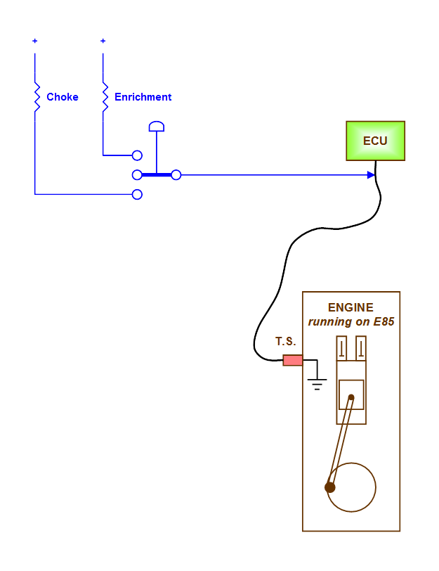
When the engine is warmed up ceases CSD totally to affect the sensor. CSD is controlled by engine temperature - not by time like SSC does. The applied voltage depends on the temperature sensor predetermined voltage levels and is suitable for my car but can be adjusted by selecting other resistance values. The levels are proportional, ie the additional applied voltage is a percentage addition and does not vary with the outside weather conditions. The principle has I named ”voltage injection” and can best be studied as shown below.
CSD works fully automatically and the choke is controlled by temperature. If the outdoor temperature is higher than +60 degrees is the choke deactivated, but is it lower will the choke be activated in batches under 5 seconds. The enrichment starts softly after about 20 seconds and stops when the engine temperature reach 150 degrees.
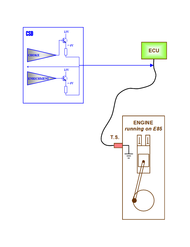
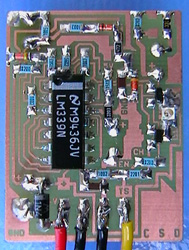
In order to be able to size R10 and R11 must one know the pull up resistor for your particular vehicle. Although the voltage when the enrichment shall expire may be good to check. Please test the measured values in this excel program.
A belated tip about CSD is how to increase stability for the enrichment circuit? Both the choke and enrichment shall hold 5 volts almost exactly over R10 and R11 - independent of supply voltage variations. For the choke is it not a problem because D5 is a zener diode and R10 is safe then, but that is not the case for R11. The voltage over R11 will vary if the supply voltage varies. As a rule, one has to check that it really is 5V over R11... Another way is to add a zener diode also to the enrichment circuit so it becomes stable too. Thus can a zener at 10 volts be attached after R8 - to ground. And at the same time also change R8 to 1k, instead for 10k. This will increase the stability 20 times regarding R11. The total resistance of R12 and R13 is then approximately 210k (provides approx. 5V across R11). For UCSM applies the same reasoning but R8 and D5 is called R6 and D10 there, parallel resistance = R8 // R9, and it also exist a diode, namely D9 - where a zener chip diode can be placed instead.
If you want to look closer on this thing you can download it here:
In the zip-file can you find everything required to implement it (manuals, diagrams and PCB-files)
- except to realizing it.
| CSD#B-1 |
# A-1 The newest audit so far.
# A-2 A minor change has been made regarding R3 and D3. During the development did not D3 correspond to the standard variations. D3 is now a 5.1 volt zener diode and R3 is equal to 2.7 kilo ohms. R10 has been changed! See NBR33.
# B-1 This is a change that required a new layout. Most of it is the same except that the pattern been modified at T1 and adjacent to C4. The upgrade applies to the fuel enrichment dynamics. It is safest for an external circuit such as CSD to manipulate soft and gently with slow voltage changes in order not to causeconfusion in a vehicles control electronics. Both A-1 and A-2 had already enrichments that began softly but its termination was however a transverse return to normal temperature. This now preceded approach caused no apparent problems for my car but it's possible that other vehicles not is equally indifferent there? The standard is however now that the enrichment both starts softly and ends softly, using time delay á la RC filters. The relocation of C4 created the biggest mess, even though only one component has been added - a diode D4. R14 now provides a gradual return.
CSC - is a precursor to CSD but not as clever
Cold-Start Circuit - facilitates cold-starts and enriches the engine with extra fuel during the heating phase. In that way is it possible for cars with mechanical-made ethanol conversions such as fuel pressure increase or larger fuel injectors to work more smoothly, much like when the car was fuelled with gasoline. Previously, I have developed modules implemented in IPE units that fixes both the choke and with time or temperature control the enrichment. One of these modules (ACM) can also be supplemented to work with the engine temperature sensor.
As regards the so-called cold-start resistances - fixed resistances or thermistors as ntc-resistor which will fool the fuel computer/ECU to think that it is colder than it is - will require to breaking up or cutting the regular cable for soldering these. This circuit only need to be soldered or attached onto the ordinary temperature sensor warm side in order to function.
When the engine is warmed up ceases CSC totally to affect the sensor. CSC is controlled by engine temperature - not by time like SSC does. The applied voltage depends on the temperature sensor predetermined voltage levels and is suitable for my car but can be adjusted by selecting other resistance values.
CSC works fully automatically and the choke is taken from the AC module as I first developed for the IPE circuits. With the USE module (up-step enrichment module) avoids high idle at start due to large enrichment. Enrichment going in and out distinct, but USEM allows the enrichment to gradually increase during about 15 seconds after starting. In that way has the control box/ECU time to adjust the idle speed down. CSC works very well in all circumstances, and for my car is CSC much better than SSC.
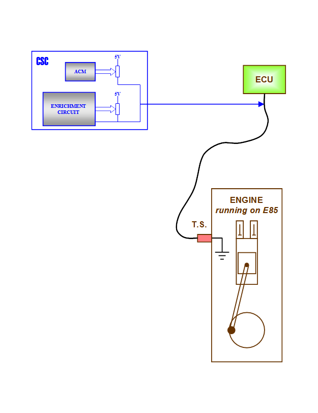
If you want to look closer on this thing you can download it here:
In the zip-file can you find everything required to implement it (manuals, diagrams and PCB-files)
- except to realizing it.
| CSC#A-1 |
# A-1 The newest audit so far. R10 has been changed! See NBR33.
SSC - simple control of choke and fuel enrichment through the temp-sensor
Smart Sensor Circuit - this variant is simpler in structure than the CSC/D and works pretty good. The principle with voltage injection also applies here. SSC is the first design that I invented, but does not always work so well. The method with a gradually decreasing voltage in the choke as well as in the enrichment phase can cause problems in an ECU. It can be confused if the voltage over the temperature sensor varies in an unnatural way, and this may affect the idle speed. Conversely can the idle rise sharply just in the moment after starting, especially when it is cold outside.
Although this circuit only need to be soldered or fixed to the ordinary temperature sensor warm side in order to function, plus the supply etc. As CSC/D will also SSC end up to affect the temperature sensor and it will happen with a gradually decreasing.
The action of the applied voltage of the temperature sensor mimics current during charging of a capacitor. First, goes it fast then slower and slower. This corresponds to a high voltage that in time slowly falls to zero. This is equivalent to an inverse exponential sequence which means that the principal function of SSC is time controlled.
Later adapts SSC to the sensor state - is it already hot (the engine is hot), so will the influence of SSC get smaller. For example: If the engine is heated with an engine pre-heater needs no ”choke” - SSC adapts to the prevailing circumstances and the voltage is then reduced.
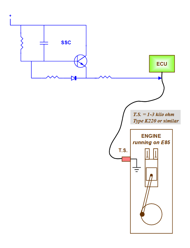
Besides, SSC does not require any external attention - it takes care of itself. Maybe you want to adjust the time of the enrichment phase or start a new choking? This is therefore already prepared with a number of options and modules.
To clarify: One may want to adjust the enrichment time or set it low. If one set it to zero will the choke only last for a few seconds then will the voltage decreases quickly and after about 5-10 seconds is SSC completely off.
Like CSC/D will also SSC functions only if the temperature sensor has one connection to chassis ground.
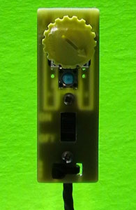
The last module has I baptize to SAM (smart adjustment) and consists of the useful 393 plus some resistances (and an e-lytic). SAM ensures that the idling not is rushing since the choke willingly holds the voltage on the temp sensor. In addition will SAM speeds up the enrichment, whether it is summer temperatures. SAM is almost a must if SSC will work flawlessly as a cold start aid, and which I understand is SSC with SAM still a pretty smart solution even though it is now more than six components (as shown above). Eight with the SA module, seven with SSC plus six with the ”complement” - that's a total of twenty-one.
If you want to look closer on this thing you can download it here:
In the zip-file can you find everything required to implement it (manuals, diagrams and PCB-files)
- except to realizing it.
| SSC#A-2 |
# A-1 The newest audit so far.
# A-2 After prolonged tests with SSC has it been found that the idle rises alarmingly at cold starts if the temperature is above about 30 degrees. To deal with this problem one should use the module SAM (smart adjustment module). In the module is also a circuit that automatically turns down the enrichment time if the outdoor temperature is above +60 degrees. SAM can be seen as a complement and can always be applied to an already completed SSC-unit. R5 - that is related to the complement-circuit which switches from 5 to 6 volts at increasing cold (+20 degrees), is now set to 820 ohm.


