Can be used in both multi-point and sequential systems.
The G-series is a smarter alternative than my previous works. It usually become so that it takes a few prototypes before it sits down. G-series forcing the injectors to be open for a longer time - so what say the computer about that? Since most fuel injection systems in cars not have better control on the driving transistor, so does it not matter? The computer does not know what is going on but if it shows up an injection ditto that makes it, ie would feel the fuel injectors - then we can have a problem! It may well be that there may be multiple computers in a car and one of them may focuses solely on what the other systems are doing? However, there is actually possible to organizing an injector with a diode and a resistor which simulates an injector coil. Thereby circumventing we that problem also.
It is convenient if you do not need to break the link spreader/computer, but if you has additional connectors to their injectors can you with non-existent interference achieve a separation, but it becomes a bit more cables to keep track of. If you happen to be in possession of the ordinary multi-point injection principle, which is based on one transistor, then you only need one cable: One cable from an injector and forward to this circuit - it's not so bad?
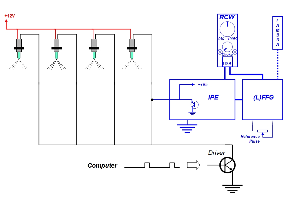
You do not have to worry about the power supply to the IPE-GS. The cable that controls the fuel injectors have a second task, namely to supply power to the device. The voltage and the current is drawn from the injectors and converted to 7.5 volts. The power consumption is small and with all additional modules plugged, prefer this most 50mA, but are usually less. This supply works fine even if you have high ohms injectors. The supply unit of IPE-GS does not affect the resulting spikes that occur when an injector is closed. Voltage spikes are a part in the design of injectors and should usually exist.
The pulse-width accuracy is as high on the G-series as it is for any other of similar constructions, even if the outdoor temperature varies - and I have of course checked this.
Furthermore, is the G-series based on MOSFET transistors, not IGBT transistors - which is more expensive.
A significant advantage of the IPE-GS is the potentiometer that controls the pulse extension also are able to control it for other devices. What I am talking about is the SQ module. This module is used if somebody has a sequential system in which each injector must have a separate controller. SQM is smaller than the IPE-GS, which I moreover calls the baseboard. It is always necessary with at least one IPE-GS-baseboard unit. You can actually just have a ”baseboard” and get to a working pulse enlarging device - as long as the car not has a sequential system.
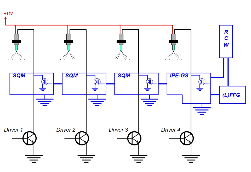
From a substantial advantage, till a key difference from earlier versions, is the ability to achieve a fully automatic fuel regulation. See ”automatic fuel regulation” for further study.
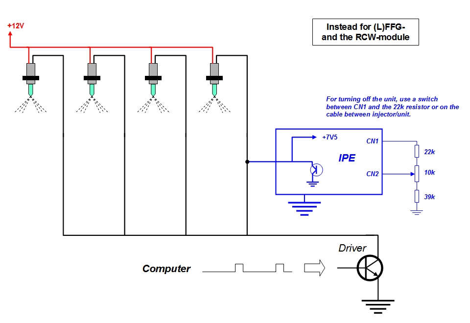
At last should I show how to proceed if you do not use any accessories, but is only interested in getting a workable design, which solves the problem of low entry of fuel (one channel multi-point car).
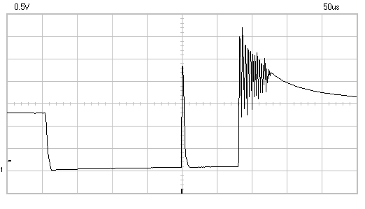
An oscilloscope image shows how the spike pulse appears between the regular pulse and the additional pulse. Note that the opening time is very short here, otherwise it is difficult to capture it.
Another oscilloscope image shows the system controller pulse, inter alia, located at the base belonging to T3. A good way to find fault in T3 or any other component, is to see if the system controller pulse actually exist.
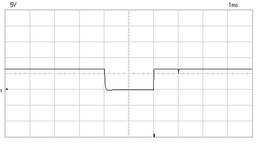
The oscilloscope image of IPE-GS which operates with a fuel injector can look like this. Depending on which zener diode D1 that has been selected, so will this component determine the look of the voltage flukt-rations. If you choose a zener diode that can withstand high power is the transients larger than if you choose one with lower power. For this image I have select the diode 1N5368, but on the first oscilloscope image were it BZT03C47.
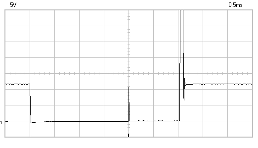
If you choose to use T5 you can improve the performance of the circuit by testing high values on C4. I tried with 3300n which gave extra high linearity. C4 does not necessarily have to be a plastic capacitance - cheap electrolytes also work, but can be a little soggy, in addition the D9 should be changed to a Schottky diode.
Attempts have been made with the more temperature-resistant comparators LM293 and LM2903. Even the military type LM193 has been tested, but none of them works here! What I have found is that this electronic arrangement demand specific requirements on certain components. These three more suitable comparators simply do not fit here. If R6 changes from 1k to 2k7, it will work tolerably but the extra pulse will be too short and the function can completely terminate if the supply voltage drops. So, the SMD variant LM393M is applicable and it seems to work satisfactorily down to -18°C.
However, the more temperature robust IC circuits LM293, LM2903, LM239, LM2901, LM258, LM2904, etc. are advantageously used for my choke and enrichment modules - including AUTOGM, LMD, CSC and CSD. We are talking outdoors here and apparently this detail has overlooked me for several years...
If you want to look closer on this thing you can download it here:
In the zip-file can you find everything required to implement it (manuals, diagrams and PCB-files)
- except to realizing it.
| IPE-GS#A-4 |
# A-2 A new module named AFE has been added (110620), but this module does not require any other modifications more over to connect it. AFE stands for Automatic Fuel Enrichment and ensures that the car gets about 15% more fuel before the engine is running hot. When the engine is hot enough returns the system to normal amount - as if AFE not had existed. AFE is controlled by an NTC resistor that must be mounted on the engine block.
# A-3 The modules AC (auto choke) and AFE (auto fuel enrichment) has become invaluable, so therefore I recently designed (1206) a custom module for IPE-GS (but only for multipoint systems) which holds both functions. This module is called ACF and is originally from IPE-GP. The ACF is designed for temperature-enrichment not time-based enrichment, as IPE-GP is.
# A-3 A minor upgrade has been made 1207. New information concerning this NTC resistor. One might as well use the car's own temperature sensor so you avoid making one more. This feature applies ACF module to GS and S. Thus, the ordinary temperature sensor can be connected instead of that the picture shows, unless one not let CSD take care of the choke and the enrichment?
# A-4 NTC expires because it is unnecessary. NTC did not appear for a minor temperature deviations, instead they became larger. In the spring 2017 accomplish careful testing of the drift causing by different temperature and I found that T5 causes major drift (greater than NTC). The function for T5 has not been changed in sequential systems but its task has been taken over by a regular NPN transistor - BC546B, and not as before with a Darlington transistor - BC517. When T5 is used, R12 should assume the fixed value 12k ohm and R52: 22k ohm. In sequential systems requires better decoupling for the supply voltage 7V5 and for CN6, which not has been noted before. LM393 for the specific IPE function can not be replaced by LM293, but for all other modules based on LM393, LM339 or LM358 - changes have been made. The changes include IPE-GS, IPE-GP, IPE-S, AUTOGM, LMD, CSD, CSC and SSC. These IC are replaced with LM293, LM239 and LM258, which are better adapted for the prevailing outdoor climate.

