As the name suggests is it possible to make a package of this concept. In cars with multi-point fuel injection is everything so simple and since that the G-series support it selves through the injectors, is it possible to simplify the cable arrangement substantially.
This model works only for multi-point system, but can actually be made to work in sequential systems as well. In that case requires a number of SQ modules and which also is integrated with IPE-GP. I will not explain that arrangement her but it's the same type of connection as it is for IPE-GS.
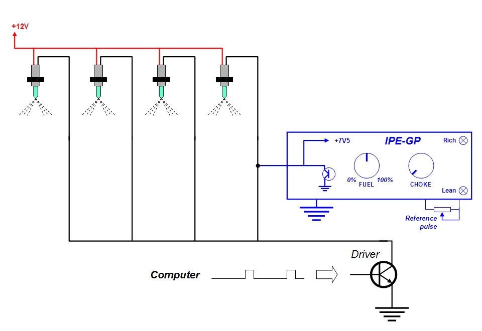
IPE-GP is supposed to be located in the cockpit so that it becomes accessible to the driver and when it is rather small (50 x 80mm) does it not take up much space. However, should you build it into some sort of box first.
Have you instead choose IPE-GS is there no reason to even think about this project.
In the autumn of 2011 I managed to build this circuit. It turned out that it was not quite optimal in its first version. An inadequate grounding of the C4 made the system unstable. After a lot of optimization work, is now all problems hopefully eliminated? In addition is an ACF module added. With ACFM gets an automatic choke function and automatic fuel enrichment during cold engine. If you choose to remove the LEDs (which indicates high, low or normal opening time) becomes IPE-GP fairly simple to build. You can thus choose to either use the FFG circuit or skip it. Although, the power switch may seem unnecessary if one instead has a two or a three pole connector? In that case, just pull out the IPE-GP from it if you want to turn it off? Of course you can also choose whether to use ACFM or not? If you decide to exclude the FFG circuit, one not need to do any ”preliminary investigation”. The purpose of this is mainly to get the LEDs to behave rationally. The LEDs should preferably be switched off when driving the car on idle, for it is only at a certain idle speed and at a certain engine temperature that one can make accurate comparisons.
If one thinking of which type of contact that IPE-GP should be connected to, are power connectors to computers not that stupid. Thus, it is probably an advantage if you easily can take your pulse-extender with you without having to unplug the cable from the cabin, to the engine compartment and loosen its connection to the injectors? This is the cable/connectors I meant:
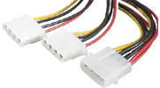
Another variation is to connect the cable from the IPE-GP with cable lugs or some other small contact in the appliance box, but this may be a little crowded...
If one build an appliance box as described, one can decorate the front with a panel. The panel is printed out with for example Photoshop and can then be taped to protect the paper from moisture and more. There are four versions depending on whether an FFG circuit exists or not, and also for labeling applicable to throttle or real extension:
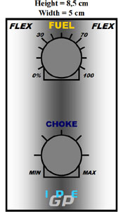
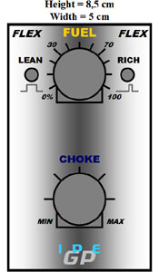 0-100%
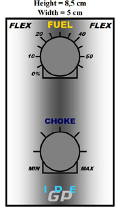
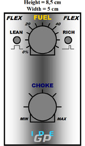 0-55% (real)
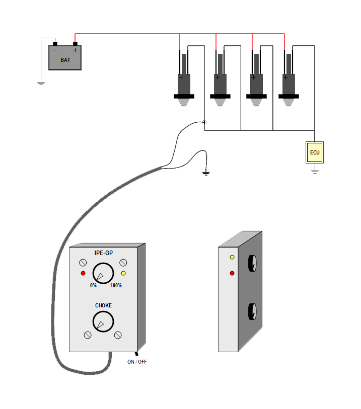
The figure below shows a lifelike sketch of a finished design, but also illustrates how easy it is to install an IPE-GP. You can also attach it to an angle and therefore one can put the LEDs in a different way.
Attempts have been made with the more temperature-resistant comparators LM293 and LM2903 for this circuit. Completely in agreement with IPE-GS are these variants not suitable, even though they should be better. Perhaps they are not as sensitive as LM393, which could be seen as a requirement for this circuitry to work? It is the same problem for the SMD variants, as described under IPE-GS. So, the LM393N is applicable and it seems to work well all the way down to -18°C.
If you want to look closer on this thing you can download it here:
In the zip-file can you find everything required to implement it (manuals, diagrams and PCB-files)
- except to realizing it.
| IPE-GP#B-2 |
# A-1 Is the first audit.
# B-1 Autumn 2011 were carried out some improvements. The grounding of C4 has been redesigned - C4 must be grounded near the comparator. R3 has been changed to 150k. The position D1 had was incorrect, but is now correct. Both of the decoupling on the ground plane has been excluded. A module has been added: ACFM can be mounted over the base-board and supplies this pulse-extender with automatic choke and automatic fuel enrichment during cold engine. In addition, have a lot of details been adjusted.
# B-2 In the autumn of 2012 found I more flaws in the design. Some interferences appears when one wish to increase the linearity of this pulse extender. This has to do with its compact layout, which places greater demands on the ground couplings. For this reason is the ground plane in the layout changed (the upper part) and a (minimal) change even at the component side. The rings that mark the soldering on both sides must be followed carefully! Some older copies of LM393 does not work well in GP, but new brand of the hole mounted version works fine. The components R12 and R6 (ACFM) will be raised one step if C4 are shifted from 1000nF to 2200nF - 33k and 220k instead of 27/150.

