This is a very simple but interesting circuit, which realizes the extension of an injector pulse, without that too many electronic components are involved.
IPE-S works quite nonlinear; it means that when setting the pulse extension for example 40% at idles - so it will always give 40% as long as not the injector time increases significantly. Let's say the opening time of an injector or several injectors increases (ie the engine requires more fuel), at the same time will IPE-S put in more extra time so not the mark-up (here 40%) become smaller. This is performed of IPE-S continuously and consistently, but the mark-up is not entirely proportional and the larger the opening time becomes, the greater becomes the deviation down from 40% - maybe 35% in the case of a large load change. Despite this inconvenience, it usually operates without any problems. What may happen is that the car may cough a little when you step hard on the accelerator. For small load changes is IPE-S over-linear, ie the fuel-amount will increase a little beyond 40%.
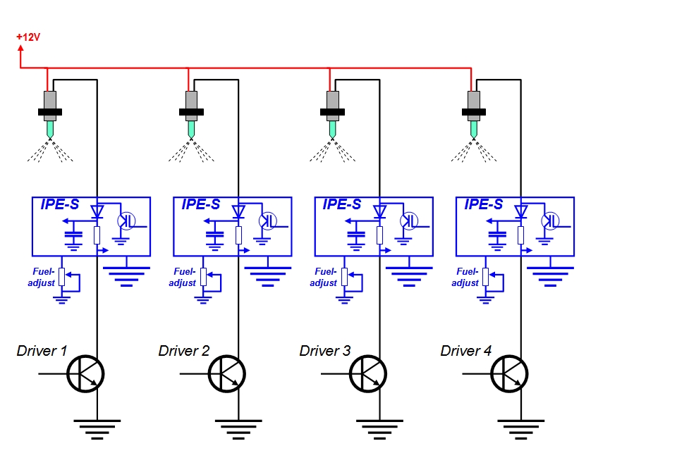
IPE-S was originally developed to be used in sequential systems, but of course will it work at an ordinary multi-point system as well. Shall it be used in sequential system, ie one (1) unit for each injector can it (due to its small size) be placed near or close to this, though it might as well be placed elsewhere, perhaps near your ECU? If you find your ECU and has a multi-point injection (one channel) would it be pretty easy to connect it - precisely for this purpose is now both a choke and an AFE module available, to supplement with.
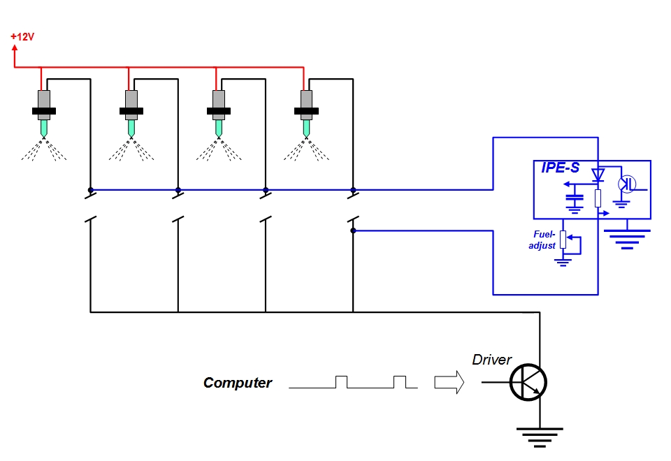
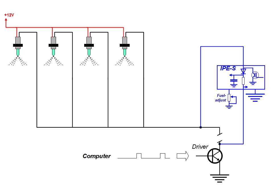
Although IPE-S need a RCW module but in this case is it enough with a cable (2-pole) and a potentiometer.
This method is necessary to resort if not the ECU is available and if it applies to an ordinary multi-point system.

Is the ECU is available and you have a multi-point system, so is there less tampering if you make it like this.

And this is the procedure if you have a sequential electronic fuel injection system.

IPE-S draws all its power from the system it is connected to, and the arrangement permits that a large capacitor always is connected to the injector cable - in series with a diode. Despite the capacitor can the spike-like positive voltage-surge not be stopped close to the injector/injectors. The magnetic flux that emanating from the fuel injectors inductive character is quite strongly and specifically from low impedance injectors. The solution is to cut the rising voltage trend with a zener diode - this is necessary to prevent IPE-S being damaged by a too high supply voltage.
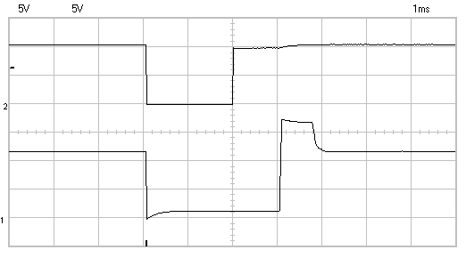
Here's how it looks on an injector cable via an oscilloscope and that one can see (the lower of the two) is that the voltage tends to rise immediately when the injector turn off, but when the zener diode is there, smoothed the voltage out. The pulse extension is about 50% in comparison with the reference pulse above.

For my car one can use a zener diode labeled 15V, but if the transients are sharp, you can choose 18V or even 24V? The diode can become hot if it has to take care of powerful transients in an early stage. If one wishes to go over 20V required in addition of using D3, that one choosing R01 to 1W and R12 in the RCW module to 2.2 kilo ohm.
Even for an LM393N, it may sometimes be difficult to achieve enough pulse width. It is primarily a brand that overshadows everyone else and it's the chip manufacturer ST, but the one named A9048 is not good, but it's F26050. The reason for and where/how this variant can be obtained I have no knowledge of. One can also try different SMD variants of LM393 when an printed board now is available - that adapt an SO8 to a DIL8.
If you want to look closer on this thing you can download it here:
In the zip-file can you find everything required to implement it (manuals, diagrams and PCB-files)
- except to realizing it.
| IPE-S#B-1 |
# A-1 The newest audit so far.
# A-2 This change occurred 2011-08 and supplement with a new RCW module plus a built-in choke - where even an AFE module adapted for IPE-S is included.
# B-1 In late August 2011 I discovered a few errors that now are fixed. The supply voltage is due to the size of the transients and can be controlled with D2. The value of D2 has thus been changed! D3 is a new diode that protects the gate of the MOSFET against over voltage. R7 and R11 are somewhat vague and may vary slightly. There are now two AFE modules, the new AFEa is controlled by a time circuit that is activated by the choke and thus not require any NTC resistor.

